
12 hard drives and 5 SSDs in the Thermaltake W100 case 
EKWB watercooling for the TR2950x
Ever since Apple announced that they were going to switch away from Intel processors in favour of ARM, I’ve been considering making the switch myself as well. Ryzen is fast, but I’ve had issues with my TR2950x pretty much from the day I built it, and Intel seems intent on kicking the overpriced Broadwell / Skylake 14nm++++++ can down the road forever; and with ARM starting to pick up steam in the server market, I thought it might be about time I take a look at what’s available in the consumer market.
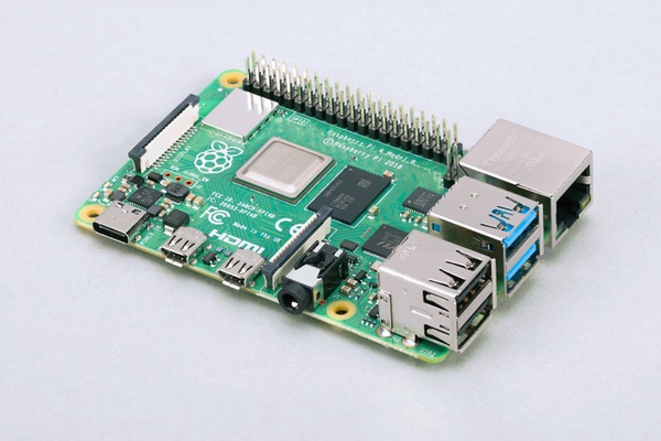
I’m sure everyone knows what a Raspberry Pi is at this point, but two things that it’s not, is a router or a server. MicroSD is slow, eMMC is slow, the platform doesn’t even support SATA, and gigabit ethernet is also slow comparatively to 10 gigabit (and you only get one network port).
Getting into ARM seems to be quite a niche still, despite the fact that practically everyone owns a cellphone, or a tablet, or a smartwatch these days… not to mention consoles like the Nintendo Switch, the Nvidia Shield family, or the multitude of retro-themed “mini” consoles on the market.
If you’ve ever installed DD-WRT / OpenWrt on a wireless router, or installed CyanogenMod / LineageOS on an Android phone, you’ll know that it’s not an easy task to run your own code on them. Tinkering with most ARM devices is sadly the same way for the most part. The Raspberry Pi comes close to being open, but it still has its own firmware that you have to deal with, and none of this stuff is standardized.
I spent several months trying to find an ARM board that was relatively inexpensive (compared to x86), and had decent performance. ARM hardware development seems to come in waves, and we could be nearing the tail end of a lull if ARMv9 is coming soon (it was recently announced in March).
I didn’t want to wait until next year (or longer), so I settled on ARMv8. Eventually I found a board that had both 10 gigabit networking and SATA for storage. Enter the Marvell / SolidRun Macchiatobin.

This board packs two 10 gigabit ports for either copper or fibre / SFP+ DAC cables, a 2.5 gigabit SFP+ port, as well as an additional gigabit copper port. Perfect for running a router for a home lab. Add in the three SATA3 ports, and you have a storage server that can easily saturate a 10 gigabit network if you are using SSDs for storage.

The “mcbin” is powered by a Marvell Armada 8040 system-on-a-chip, which houses four ARM Cortex A72 processors clocked at 2GHz (or 1.6 for the cut-down “SingleShot” variant – which also drops the copper 10 gigabit ports), and supports up to 16GB of DDR4.

All of this power is contained within the Mini-ITX form factor, which means it should fit easily into any PC case. Speaking of power, both variants can be powered by either a 12V wall wart, or with the onboard ATX power connector. The wall wart (included separately) outputs a maximum of 2.5A, so the mcbin only consumes a maximum of 30W. My TR2950X idles around 200W, so I could run 6 of these at full tilt for the same amount of power.
This thing sounded too good to be true, but I was curious, so I bought one. Shipping was quite quick, and the board was well packed in thick foam. I wish all computer parts were packed like this, the packaging for a PC motherboard has zero protection whatsoever if UPS / Fedex decide to play soccer with your shipment.
At this point I was quite happy with my purchase, even though I hadn’t even powered it up yet.
In part 2, I’ll go over my experiences in getting Gentoo running on the board, and in part 3 I’ll talk more about my plans to switch my home lab over to ARM processors.

