Moving to ARM (Part 3 – Upgrading the firmware)

(Continued from Part 2)

So after rebooting back into the 4.x kernel, I started looking into what it takes to upgrade the firmware on the board. It was around this point where the technical wiki (which is either maintained by Marvell, or Solid-Run… I can’t tell which) started to fail. If I had to guess, they upgraded the underlying PHP on their webhost without checking to see if their webapps supported it. (It’s still broken to this day, but some of the (slightly outdated) information has eventually been transplanted to another wiki.)

Upgrading the firmware isn’t terribly hard, but I would only recommend doing it when you have to (ie: if you want to ever use a kernel newer than 4.x), I’ll touch more on that later. The firmware is made up of a few components:

Setting up the build environment was a piece of cake, since Gentoo already has a full toolchain ready to go. Or at least that was the case a couple years ago. Current ATF git head won’t compile with GCC 12+ or binutils 2.39+ [1] [2] [3], but as long as Gentoo still keeps the older packages in the portage tree, you can switch back and forth as needed with “eselect”.

eselect gcc set aarch64-unknown-linux-gnu-11
eselect binutils set aarch64-unknown-linux-gnu-2.38

It turns out ATF ships their own version of GCC to build the firmware with. I don’t see why they do this, because regular GCC used to work just fine… but I digress.

The build script looks something like this…

#!/bin/bash

BUILD_DIR="/root/mcbin"


cd "$BUILD_DIR"/u-boot
make distclean
make mvebu_mcbin-88f8040_defconfig
make -j4

export BL33=$BUILD_DIR/u-boot/u-boot.bin
export SCP_BL2=$BUILD_DIR/binaries-marvell/mrvl_scp_bl2.img
export MV_DDR_PATH=$BUILD_DIR/mv-ddr-marvell

cd "$BUILD_DIR"/arm-trusted-firmware
make distclean
make -j4 USE_COHERENT_MEM=0 LOG_LEVEL=20 PLAT=a80x0_mcbin all fip mrvl_flash

cp "$BUILD_DIR"/arm-trusted-firmware/build/a80x0_mcbin/release/flash-image.bin "$BUILD_DIR"

Compiling the firmware only takes a few minutes once the repositories are all checked out and ready to go. When you’re done, you have a shiny new “flash-image.bin”, but how do you go about installing it?

Inside U-Boot, Marvell included a command called “bubt”. I couldn’t tell you what that stands for… Regardless, you have to have the bin file in a place where U-Boot can read it, which usually means the eMMC, you may run into issues if the file is on a USB stick for some reason… at least I seem to recall that being an issue at one point.

So “bubt flash-image.bin spi mmc” and you’re done right? Well, not so fast. After running “reset” to reboot U-Boot (or power-cycling), you’ll probably notice your U-Boot environment variables are all gone, which includes your kernel bootcmd config lines, as well as your ethernet MAC addresses. Probably should have saved those somewhere, but it wasn’t documented anywhere on the wikis.

Thankfully, I had ran a “printenv” in U-Boot before running “bubt”, so I was able to scroll back in my terminal, re-entering my missing variables, running “saveenv” to make sure they get saved, and rebooting again. I suppose I shouldn’t be that surprised, because the same thing happens on x86 when you upgrade your BIOS. You would think that after 40+ years of computing that this kind of thing should persist upgrades, but I digress again.

Now I mentioned earlier that I would only recommend doing the firmware upgrade only when necessary. There was a time when I was checking the firmware repositories every couple weeks for updates, that was a mistake on my part. At some point I had pulled a version of U-Boot head which broke SDHCI support, which basically meant it couldn’t boot any kernels off eMMC or USB.

Thankfully for those jumpers I mentioned back in part 2, I was able to temporarily jumper the board to booting U-Boot off the SD card, flashing an older firmware back to the eMMC, flipping the jumpers back again, and try to figure out where things went wrong with U-Boot.

I didn’t know who to reach out to initially, because U-Boot doesn’t really have a support structure, but I found a relevant commit by a friendly gentleman called Marko, so I emailed him to see if we could figure something out. Turns out he didn’t have the same board I did, but the issue also affected several other Marvell boards he owned, which seemed to point to an issue in the Xenon SDHCI driver. A couple weeks later, a patch was merged… I tested it and thankfully it was working again.

I should probably write a part 4 at some point, since I’m kindof glossing over a lot of the minor details, like what devicetree files are for, how the kernel and U-Boot have their own files, and how they should probably stay synchronized if you want your stuff to work correctly, but I’ll save that for another time.

Moving to ARM (Part 2 – Booting the board)

(Continued from Part 1)

When I first purchased the Macchiatobin, I was under the impression that they had an OS image installed on the eMMC. Boy, was I in for a surprise. Booting the board with the serial console connected gives you something like this…

BootROM - 2.03
Starting CP-1 IOROM 1.07
Booting from SPI NOR flash 1 (0x32)
Found valid image at boot postion 0x000
lNOTICE: Starting binary extension
NOTICE: Gathering DRAM information
mv_ddr: mv_ddr-armada-17.06.1-g47f4c8b (Sep 27 2017 - 11:55:40)
mv_ddr: completed successfully
NOTICE: Booting Trusted Firmware
NOTICE: BL1: v1.3(release):armada-17.06.2:297d68f
NOTICE: BL1: Built : 11:55:45, Sep 27 2017
NOTICE: BL1: Booting BL2
lNOTICE: BL2: v1.3(release):armada-17.06.2:297d68f
NOTICE: BL2: Built : 11:55:47, Sep 27 2017
BL2: Initiating SCP_BL2 transfer to SCP
NOTICE: Load image to AP MSS
NOTICE: Loading MSS image from address 0x4023000 Size 0x504c to MSS at 0xf0580000
NOTICE: Done
NOTICE: BL1: Booting BL31
lNOTICE: BL31: v1.3(release):armada-17.06.2:297d68f
NOTICE: BL31: Built : 11:55:49, Sep 27 2017
l

U-Boot 2017.03-armada-17.06.3-ga33ecb8 (Sep 27 2017 - 11:55:14 +0200)

Model: MACCHIATOBin-8040
Clock: CPU 1300 [MHz]
DDR 800 [MHz]
FABRIC 800 [MHz]
MSS 200 [MHz]
DRAM: 16 GiB
U-Boot DT blob at : 000000007fb12fb8
EEPROM configuration pattern not detected.
Comphy chip #0:
Comphy-0: PEX0
Comphy-1: PEX0
Comphy-2: PEX0
Comphy-3: PEX0
Comphy-4: SFI
Comphy-5: SATA1
Comphy chip #1:
Comphy-0: SGMII1 1.25 Gbps
Comphy-1: SATA0
Comphy-2: USB3_HOST0
Comphy-3: SATA1
Comphy-4: SFI
Comphy-5: SGMII2 3.125 Gbps
UTMI PHY 0 initialized to USB Host0
SATA link 0 timeout.
Target spinup took 0 ms.
AHCI 0001.0000 32 slots 2 ports 6 Gbps 0x3 impl SATA mode
flags: 64bit ncq led only pmp fbss pio slum part sxs
SATA link 0 timeout.
SATA link 1 timeout.
AHCI 0001.0000 32 slots 2 ports 6 Gbps 0x3 impl SATA mode
flags: 64bit ncq led only pmp fbss pio slum part sxs
PCIE-0: Link down
MMC: sdhci@6e0000: 0, sdhci@780000: 1
SF: Detected w25q32bv with page size 256 Bytes, erase size 4 KiB, total 4 MiB
Net: mdio_register: non unique device name 'ethernet@0'
eth0: mvpp2-0, eth1: mvpp2-3, eth2: mvpp2-4, eth3: mvpp2-5
Hit any key to stop autoboot: 0

So far so good, right? Unfortunately, the board did not boot, and it dumped me to a prompt. I started looking into U-Boot, and it seems pretty sensible… it also feels somewhat reminiscent of the Open Firmware that was used on PowerPC Macintoshes, or Sun SPARC systems (among other older UNIX bootloaders). I was able to look at the filesystem on the eMMC, and it was definitely blank. Well darn, what do I do now?

The board has a block of jumpers to choose how the board boots up. It’s a good thing… because I’ll need it later (foreshadowing). I thought I would need it now, but U-Boot can boot from the SD card as long as it can see it. I’ll touch more on that in part 3.

So I had a look online, and on their website, they have a kernel image listed, as well as a few distro options available for download. The U-Boot firmware is dated from 2017, the kernel had a date of 2018 (but is also from 2017), and the distro images are from 2015-2016. In the grand scheme of Linux things, this software is ridiculously old (even for 2021), but I didn’t want to stay on it forever. I also didn’t have a way to copy the images over to the eMMC, so my only option was to copy them to a SD card, and boot from that instead.

I was able to get buildroot installed on the eMMC, but if I recall correctly, I didn’t have what I needed to install Gentoo yet. Unfortunately this next part gets a little sketchy, because this was a few years ago now and I didn’t document it at the time.

The next plan of action was to install Gentoo to the eMMC itself. Only problem was that the eMMC was only 6GB after formatting (I believe the SPI boot option uses a part of the eMMC for its storage), so I resorted to using a pair of USB sticks to supplement the eMMC to get the install done. The portage tree takes 1GB on average (excluding downloaded package files), the kernel source takes a few GB as well when its all unpacked and built, so there was no way it was going to fit on the eMMC on top of the standard system packages.

Initially I wanted to use the eMMC as a “recovery partition” and install the live environment onto SSDs. This took a few days to say the least. If it wasn’t bad enough that the board is a 2GHZ quad-core ARM, using a USB stick like it’s a hard drive will lead to it slowing to a crawl (and possibly even hanging indefinitely… I wound up throwing out 4 USB sticks trying to install the other 2 boards). It would have also helped if I knew which devices I needed to add to the kernel, thankfully most of the kernel stuff has been mainlined.

Eventually I got to a point where I was ready to reboot into the newer 5.13 kernel booting off the eMMC…

mvebu-cp110-comphy: unsupported SMC call, try updating your firmware

and with that I had no eMMC/SD, no network, and no SATA, basically nothing. Well, back to the drawing board… and by drawing board, I mean booting off the SD card again.

In part 3, I will go over how to upgrade the firmware on the board, so we can get the eMMC and SD card working again (because I’ll have to do this a few times… even more foreshadowing).

NES power board – now with type C!

While I’ve been mostly happy with the NES USB power board I made a couple years ago, I have noticed power sags when the console is loaded down with 2 wireless controllers, and an Everdrive. Some of that could be due to a crummy USB cable, or the resistor (or dead short) on the data pins not playing nice with my 3A charger.

Nonetheless, I decided to upgrade the design of the board to use the USB type C Power Delivery spec. Assuming an adequate charger and cable, this should guarantee 5V@3A at the input to the console. Totally overkill, but the future is now, old man. 🙂

New and improved – I hope!

I haven’t sent the gerber files off for production yet, but I can’t wait to give this new design a test…

I should really post more :)

Sorry for the long gap between posts, you could say I had a bit of writer’s block, but the actual truth was I had forgotten some of the hassle of provisioning the ARM boards.

The good news though is that I’m in the progress of cutting over to the new hardware. Some of the previous ideas went out the window (like the custom rack and power distribution), and the Macchiatobin boards stopped being sold by SolidRun despite being told they would be on sale until 2027.

If you can see this post, then you are viewing it from one of the boards, behind another of the boards acting as the router. Have a quick peek…

3 ARM systems, an ARM-powered network switch and wireless bridge, and a cable modem that is probably also ARM-powered

More updates coming soon, including a quick run-down of how I got Gentoo running on the Macchiatobin. It’s a lot easier when you already have one already running, that’s for sure.

Remote management and power control using a Raspberry Pi

Preface: This article was originally written in Summer 2021 and was never published. I was originally going to call this article Moving to ARM part 1.5, I was writing it in conjunction with the main articles, but the following setup isn’t necessarily dependent on ARM. More articles on the ARM migration coming in the near future.

I’ve seen some articles recently about the Pi-KVM project, and wanted to use something similar with the mcbin boards I’m using to build the ARM server rack I’m building.

Unfortunately two things the mcbin doesn’t have, is a display port or a power button. When power gets applied to the board, the system boots up similar to a Raspberry Pi. The firmware also doesn’t currently support shutting the board off when you shut down the OS either.

That doesn’t mean we can’t come up with something that works though. The mcbin does support a serial console over USB, and the Raspberry Pi supports GPIO. The mcbin is powered solely off 12V, however SSDs need only 5V, so I should be able to power the entire rack off a PC power supply.

A crude drawing of the power distribution layout.
Not shown: the other 7 system boards, SATA cables, serial cables, network switch and cables, the UPS, and the USB hub.

The Pi only uses 15W, so the power supply’s standby pin should be able to power the Pi even with the output power switched off. One nice feature of the serial on the mcbin, is that the console will run as long as the USB cable is connected, regardless of whether the system is switched on.

I went online and was able to buy an ATX power breakout board, two 8 port GPIO relay boards, and an 8 port USB hub off Amazon.

Everything showed up pretty quickly as usual, however upon inspection, it appears the GPIO boards have undersized mounting holes. Something to keep an eye on if you decide to build something like this for yourself.

While I was waiting for Amazon to ship the relay boards, I whipped up some test code in Python to be able to toggle all 8 relays.

Screenshot of the Relay Control System python app

With the Pi all set up and the GPIO boards wired together and connected to power, I should be able to boot up each system individually, and connect to each console all from a single machine. The Pi has 4 USB ports, and with one of them taken up by the hub, I should also be able to connect the network switch and UPS to the Pi, leaving one port left for a combo keyboard/mouse to control the Pi with.

Moving to ARM (Part 1 – Picking the board)

Ever since Apple announced that they were going to switch away from Intel processors in favour of ARM, I’ve been considering making the switch myself as well. Ryzen is fast, but I’ve had issues with my TR2950x pretty much from the day I built it, and Intel seems intent on kicking the overpriced Broadwell / Skylake 14nm++++++ can down the road forever; and with ARM starting to pick up steam in the server market, I thought it might be about time I take a look at what’s available in the consumer market.

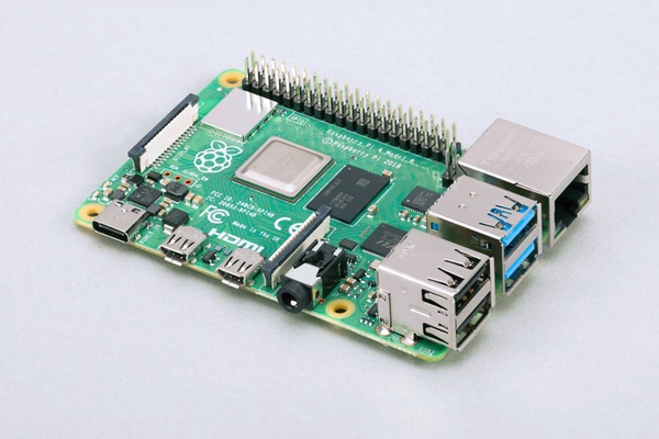
Raspberry Pi 4B – Courtesy of the Raspberry Pi Foundation

I’m sure everyone knows what a Raspberry Pi is at this point, but two things that it’s not, is a router or a server. MicroSD is slow, eMMC is slow, the platform doesn’t even support SATA, and gigabit ethernet is also slow comparatively to 10 gigabit (and you only get one network port).

Getting into ARM seems to be quite a niche still, despite the fact that practically everyone owns a cellphone, or a tablet, or a smartwatch these days… not to mention consoles like the Nintendo Switch, the Nvidia Shield family, or the multitude of retro-themed “mini” consoles on the market.

If you’ve ever installed DD-WRT / OpenWrt on a wireless router, or installed CyanogenMod / LineageOS on an Android phone, you’ll know that it’s not an easy task to run your own code on them. Tinkering with most ARM devices is sadly the same way for the most part. The Raspberry Pi comes close to being open, but it still has its own firmware that you have to deal with, and none of this stuff is standardized.

I spent several months trying to find an ARM board that was relatively inexpensive (compared to x86), and had decent performance. ARM hardware development seems to come in waves, and we could be nearing the tail end of a lull if ARMv9 is coming soon (it was recently announced in March).

I didn’t want to wait until next year (or longer), so I settled on ARMv8. Eventually I found a board that had both 10 gigabit networking and SATA for storage. Enter the Marvell / SolidRun Macchiatobin.

Marvell / SolidRun Macchiatobin DoubleShot – Courtesy of SolidRun

This board packs two 10 gigabit ports for either copper or fibre / SFP+ DAC cables, a 2.5 gigabit SFP+ port, as well as an additional gigabit copper port. Perfect for running a router for a home lab. Add in the three SATA3 ports, and you have a storage server that can easily saturate a 10 gigabit network if you are using SSDs for storage.

Macchiatobin platform block diagram – Courtesy of Solidrun

The “mcbin” is powered by a Marvell Armada 8040 system-on-a-chip, which houses four ARM Cortex A72 processors clocked at 2GHz (or 1.6 for the cut-down “SingleShot” variant – which also drops the copper 10 gigabit ports), and supports up to 16GB of DDR4.

Marvell 8040 block diagram – Courtesy of Marvell

All of this power is contained within the Mini-ITX form factor, which means it should fit easily into any PC case. Speaking of power, both variants can be powered by either a 12V wall wart, or with the onboard ATX power connector. The wall wart (included separately) outputs a maximum of 2.5A, so the mcbin only consumes a maximum of 30W. My TR2950X idles around 200W, so I could run 6 of these at full tilt for the same amount of power.

This thing sounded too good to be true, but I was curious, so I bought one. Shipping was quite quick, and the board was well packed in thick foam. I wish all computer parts were packed like this, the packaging for a PC motherboard has zero protection whatsoever if UPS / Fedex decide to play soccer with your shipment.

At this point I was quite happy with my purchase, even though I hadn’t even powered it up yet.

In part 2, I’ll go over my experiences in getting Gentoo running on the board, and in part 3 I’ll talk more about my plans to switch my home lab over to ARM processors.

How to run a NES from USB power

I recently installed a NESRGB into my NES, and wanted to remove the RF modulator from the system because I didn’t need it anymore. Or so I thought…

As it turns out, the NES also routes its power in and out of the RF modulator board a few times before sending the power to the main board to power the console. “Well that’s no good”, I thought.

NES power circuit – Courtesy of Console5

I looked around online and found an article on Hackaday where someone was doing something similar to what I was doing, however they were still powering the board from a barrel jack, and in some revisions cutting up the chassis to use a multi-out connector. I also didn’t need a palette switch since I soldered my NESRGB to the default palette. A little overcomplicated for what I needed, but still a cool project, and inspiration to come up with something I could easily use.

So I fired up Kicad and played around with a few ways to route the component video and audio out the original ports and power the console. I was quite surprised to find out that you can connect a USB host A cable into a port using the same hole that was used by the barrel jack on the original board. A couple layout redesigns later, and I came up with a fairly bare bones PCB.

My somewhat basic attempt at making a replacement board

Theoretically you could remove the LED and resistors. I had originally included it as an “idiot light” to remind me to unplug the console if I was working on it with the chassis open, but in retrospect it doesn’t really add much other than a small amount of power draw and some light shining out the back of the console (and maybe a little out the cartridge slot if you didn’t put the metal RF shield back on). The resistor on the USB connector can also be replaced with a dead short, as I misinterpreted the USB power delivery spec.

So after a few weeks of work and building one of these up for myself, I had found out that people have been making these for a while. I suppose I shouldn’t be surprised at this point, the console is 36 years old, and the NESRGB has been around for almost 10 years. That’s okay though, I needed the PCB routing practice.